WITHDRAWABLE STERN GEAR :-
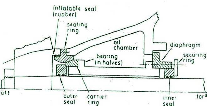
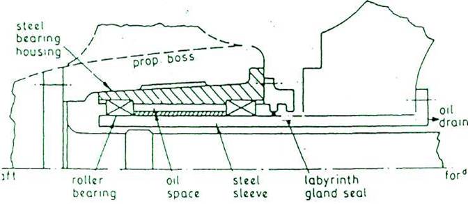
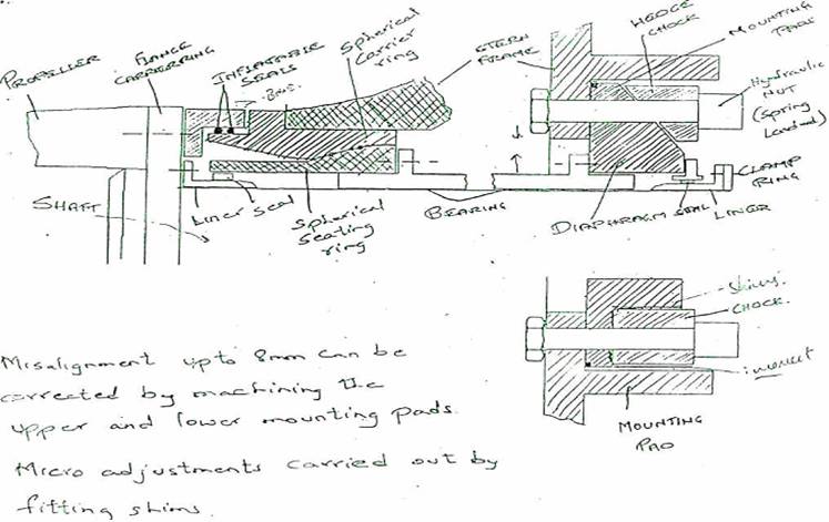
With this design, the tailshaft along with the propeller is supported by having a permanent fixture at the forward end of the propeller boss which rests on the stern frame during withdrawl of stern bearing gear. Associated with this support are inflatable seals that are used to prevent the ingress of sea water during the operation. When the seals are inflated their tightness can be checked by draining the water to inside the vessel by two pipes which are fitted to the top and bottom of enclosed cavity. The cavity is clear of water when the lower pipe stops discharging water into the m/c space. As there are two sets of inflatable seals, the same procedure is adopted for the space between the seals. When both seals found to be effective then only withdrawl
procedure can commence. If the seals are found leaking, a driver must be employed to fit an external neoprene bandage and above procedure adopted to prove that the seals is tight. The stem tube bearing oil is then drained off and the inboard seal assembly disconnected and slid along the shaft. The stern tube bearing can then be withdrawn with the assistance of horizontally mounted hydraulic jack.
ALTERNATIVE STERN GEAR
Coupling Bolts :-
For transmission of torque by flanged coupling in main propulsion shafting, coupling bolts play the major role.
The following factors are to be considered for safe and effective transmission of torque -
(1)The
coupling bolts are to be tightened to a specific value of stress, to
force
the faces of the flanges together, such that the full
surface contact takes
place and the friction between
the faces will provide some proportion of
the drive.
(2)Perfect
interference fit between coupling bolt shanks and the flange holes
is
required for maximum transfer of load. The number of bolts are to
be
designed to cam- the total torque in shear.
(3)The
elongation of a bolt when tightened under tensile stress causes
a
reduction in cross-sectional area.
Poisson"s Ratio = lateral Strain
![]()
A normally fitted bolt when tightened, because of elongation, the positive contact between the accurately reamered flange hole and machined bolt is lost. Moreover fretting can also cause damage to the bolt.
(4)An oversized bolt may be used by cooling it with liquid nitrogen to cause contraction and reduction in cross-sectional area before insertion. But the effect of low temperature and the probability of steel becoming brittle as a result of cooling is a potential danger.
(5)For parallel}' fitted bolts, slackness due to elongation can cause ovality of flange bore, reduced contact surface between bolt shank and flange hole. there can be effect of "spot facing*' misalignment which can cause additional bending stress on the coupling bolts.
(6) Number of coupling bolts and their diameter at the joining faces of the couplings is to be not less than as given by the formula,
Where, n= no. of bolts in coupling.
D=pitch circle dia of bolts in mm.
![]() u
=
specified minimum tensile strength of both in N/mm2
[carbon &
mamgenese steel =400-600 N/mm2. Alloy steel = not
exceeding 800 N/mm"] P= shaft power in KW. R= revolution in rpm.
u
=
specified minimum tensile strength of both in N/mm2
[carbon &
mamgenese steel =400-600 N/mm2. Alloy steel = not
exceeding 800 N/mm"] P= shaft power in KW. R= revolution in rpm.
(7)The minimum flange thickness at the face of the couplings should be equal to the coupling bolt diameter. Propeller shaft coupling flange thickness should be at least 0.27 x shaft diameter. The fillet radii on shaft should be 0.08 x shaft diameter for intermediate shaft, thrust shaft and inboard end of the screwshaft, the coupling flange thickness should not be less than 0.2 x intermediate shaft dia.
(8)In case of crankshaft, the fillet radius at the centre coupling flanges may be 0.05 dia of the shaft at the coupling. The fillets are to have a smooth finish and not to be recessed in way of nut and bolt heads.
(9)Where the propeller is attached by means of a flange, the thickness of flange is to be not less than 0.25 of the actual dia of the adjacent part of the screwshaft. The fillet radius at the base of the coupling flange is to be not less than 0.125 of the dia of the shaft at the coupling.
In all cases, shafting, couplings and bolts must provide resistance to astern pull.
(10) A tapered coupling bolt could be used instead of a conventional parallel fitted bolt to obtain a good fit and required tightening.
(11) The Pilgrim Hydraulic Bolt.